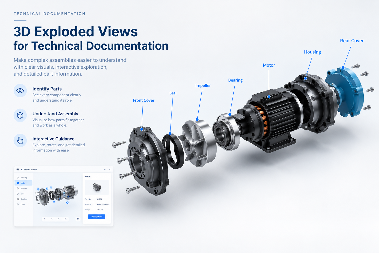
An exploded view is one of the clearest ways to explain how parts belong together.
A traditional technical publication may use a drawing, numbered callouts, and leader lines to show an assembly. This can work well, but the reader still has to interpret the drawing and mentally reconstruct the product’s three-dimensional structure.
A 3D exploded view makes that spatial relationship easier to inspect. Parts can be separated while remaining in context, allowing users to move between the complete assembly, individual components, and the instructions associated with them.
For manufacturers, the value is not simply the visual effect of parts moving apart. It is helping people understand what a component is, where it belongs, and how it relates to the rest of the product.
What Does an Exploded View Help Explain?
A useful exploded view should answer practical questions:
- Which parts belong to the same assembly?
- Where does each component sit in the complete product?
- Which parts are adjacent or connected?
- Which component needs to be identified, removed, or installed?
- In which direction does a part move?
- How do the separated parts fit together again?
These are questions about spatial relationships. That is why an exploded view can be a useful component of 3D technical documentation, especially when a static image alone leaves room for interpretation.
Static Exploded Drawings vs. Interactive 3D
A static exploded drawing can communicate a complete arrangement in one frame. It remains useful in printed manuals, controlled technical publications, downloadable PDFs, and situations where users need a stable reference.
An interactive 3D experience adds different ways to inspect the same assembly. Depending on the product and project scope, users may be able to:
- Rotate the assembly and inspect it from different viewpoints.
- Zoom into a specific area.
- Select a component to identify it.
- Isolate a group of parts without losing the larger context.
- Switch between assembled and exploded states.
- Open the product information or instruction associated with a component.
The distinction is not that interactive 3D makes drawings obsolete. It gives users another way to understand a product when spatial relationships are difficult to infer from a single view.
Connect Exploded Views to Component Identification
An exploded view becomes more useful when the visible components are linked to relevant information.
A typical interaction can follow this path:
Exploded state → select a component → view part information → return to the assembly
The selected component might reveal its name, description, supporting image, installation note, safety reminder, or related document. Where a bill of materials or part-number system is available, component labels may also be connected to those identifiers, subject to the project’s data and integration scope.
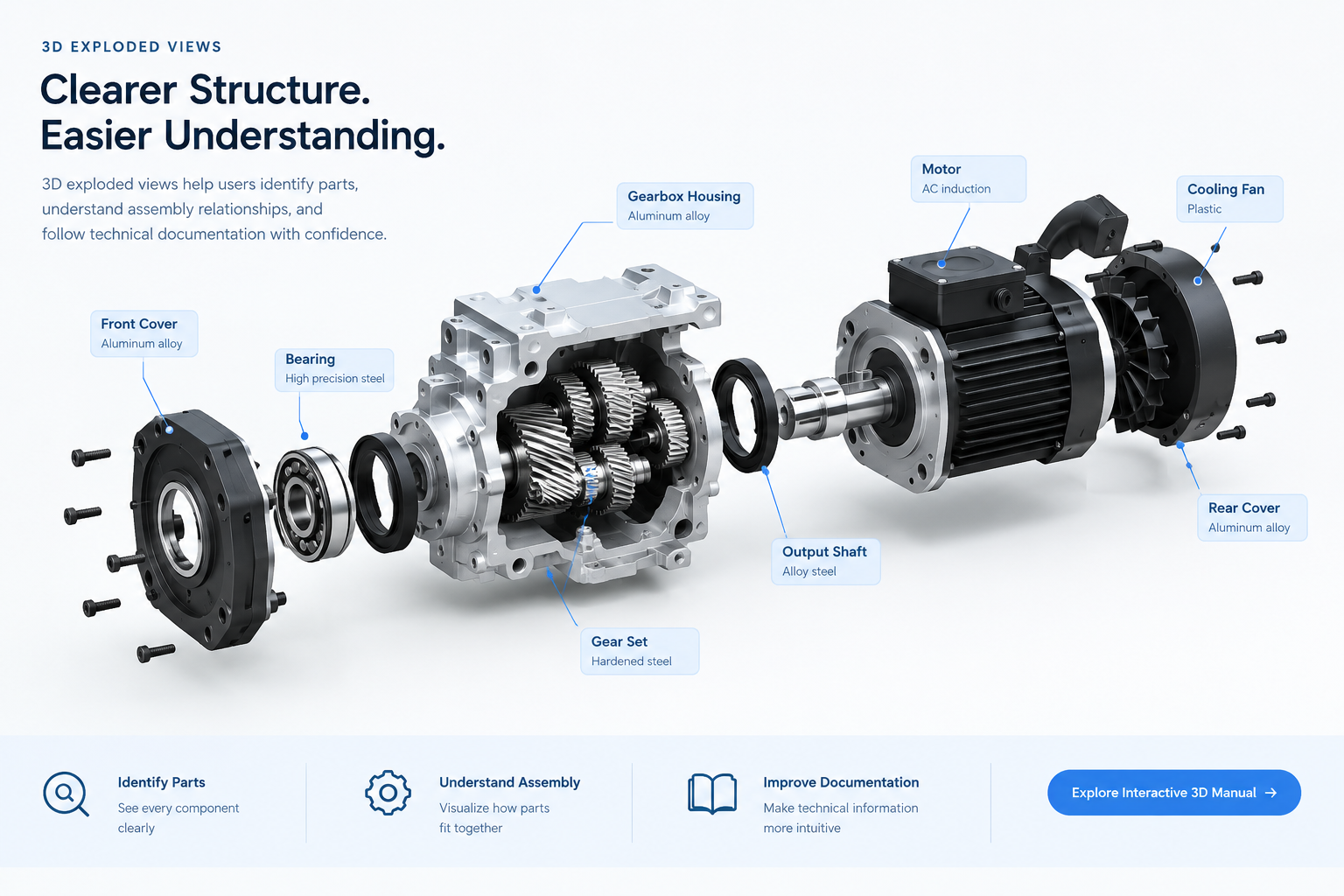
This approach is particularly helpful when several components look similar or when users need to understand how a subassembly fits into a larger product. The information appears in the context where the user needs it, rather than requiring them to search for a separate reference page.
Use Exploded Views as Part of 3D Assembly Instructions
An exploded view can also support 3D assembly instructions and 3D work instructions. Instead of presenting the exploded state as a standalone visual, the documentation can connect it to a task sequence.
For example:
Step 1 — Identify the assembly
Show the complete product and highlight the area relevant to the task.
Step 2 — Reveal the component relationship
Move to an exploded state that makes the relevant parts and their positions easier to distinguish.
Step 3 — Select the required part
Display the component name and the instruction or detail related to it.
Step 4 — Explain the action
Use a controlled animation, movement cue, or selected product state to show the next operation. The visual should match the approved instruction, not imply an unverified procedure.
Step 5 — Return to the complete assembly
Show where the component belongs in the full product so the user can connect the individual action to the overall structure.
In this sequence, the exploded view is not a decorative 3D effect. It is one step in helping the user identify a part and understand an action.
Design a Clear Exploded State
A useful exploded view should preserve enough of the original spatial relationship for the assembly to remain recognizable. If parts move too little, users may struggle to distinguish them. If they move too far, users may lose the sense of how they fit together.
A design should therefore consider:
- Component hierarchy: which parts belong to subassemblies and how those subassemblies relate to the whole.
- Separation distance: enough space to identify components without scattering them beyond recognition.
- Movement direction: consistent, readable movement that supports the assembly logic.
- Camera position: a viewpoint that reveals the relevant connections and does not hide important parts.
- Labels and selection states: clear identification without covering the component itself.
- State transitions: a predictable way to move between complete, exploded, and selected-part views.
The exploded state should remain a readable representation of the real product. The design goal is clarity, not maximum separation or visual complexity.
When Is an Exploded View Not Necessary?
Not every product or instruction needs one. An exploded view may add little value when the product has very few components, the assembly relationship is already obvious, or the task is mainly about text, measurements, or other information that does not benefit from spatial interaction.
A practical decision question is:
Will separating these parts make the user’s task easier to understand or complete?
If the answer is no, a clear diagram, photograph, table, or written instruction may be the better choice. Use 3D where it resolves a real point of confusion.
Before Building One, Confirm These Four Things
Before preparing an exploded view for a digital manual, confirm:
- The user task: what the reader needs to identify, understand, assemble, remove, or inspect.
- The source assets: whether usable 3D models, part hierarchies, drawings, and approved instructions are available.
- The information behind each part: which names, identifiers, details, warnings, and supporting documents should appear when a component is selected.
- The intended interaction: whether the user needs a simple exploded state, selectable components, a guided sequence, or a combination of these.
These decisions help keep the interaction proportionate to the actual documentation need. Model preparation, detail level, and integration requirements should be determined from the available product data and the intended use—not from a universal specification.
Add Exploded Views Where They Clarify the Product
Exploded views work best when they connect to the rest of the product information journey:
Product catalogue → find the right product
Complete 3D assembly → understand the overall structure
Exploded view → inspect component relationships
Hotspots and labels → identify parts
Component details → access relevant information
Guided instructions → understand the next action
The result is not simply a model that users can rotate. It is a more connected way to move from a product’s overall structure to the specific information needed for a task.
Explore Interactive 3D Product Manuals
INTR builds custom Interactive 3D Product Manual experiences that connect product models, component information, interactions, and browser-based guidance.